
Practice Morse Keyer
A Practice Morse Keyer - May 1992
Colin, VK2JCC found this interesting circuit by A.P. Cooper
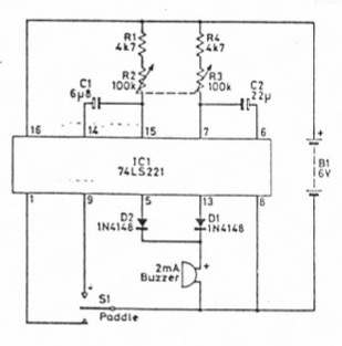
in an old Practical Wireless of December 1983. The article that comes with the circuit points out that Morse keyers need not be complicated or expensive to construct. This circuit has been designed to provide a Dot to Dash ratio of one to three, with variable speed control provided by a dual-ganged potentiometer (R2, R3 in the diagram).
The article goes on to state that construction is not critical and can equally use a pcb layout or be built on Veroboard. Unused pins of the 74LS221 may be left open-circuit. The low current "beeper" is directly driven from the 74LS221, noting that correct polarity must be observed.
In the original article, it described using an ordinary flexible
nail file to give a side-swipe action for the paddle. The nail
file is mounted on Veroboard or a piece of pcb, with two Veroboard pins mounted to form the connections of the SPCO switch with a centre off position. The article also suggest that the two pins should be gold plated pins for maximum switch reliability.
In constructing the keyer, all resistors are 1/4 watt 5%, the ganged pot is a 100k Linear, the electrolytics are tantalum. The article also states that a non-Schottky version of the IC will function quite OK with only a slight increase in current.