
Sensitive Field Strength Meter
Sensitive Field Strength Meter - Dec 1995
This field strength meter article and circuit was provided by Ray VK2FRY and comes from the Gladesville Amateur Radio Club Magazine of Feb-Mar 1995.
The meter is reported to work well from VLF to VHF. A short telescopic whip (.5 - 1m) is used as the pick-up antenna. D1 rectifies the signals and the resultant positive pulses are applied to the base of Q1 which is biased by R3 & RV1.
The meter is in a bridge circuit, the collector - emitter of Q1 and R1 forming two arms, R2 and R4 the other two arms. Current flowing through the transistor causes the bridge to become unbalanced and hence current then flows through the meter.
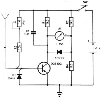
RV1 zeroes the meter by varying base current o f Q1 (and balancing the bridge). C1 bypasses the rectified RF at Q1's collector; the diode across the meter prevents it from slamming.
Only a 3v battery is needed to power the meter, Note that D1 is a germanium diode for best sensitivity, although a silicon (ea
1N914) can be used but with a reduction in sensitivity on low signal strengths.