
VUHF Preamp
A VHF or UHF Preamplifier - Sept 1994
The following article and story are courtesy of the Eastern and Mountain Districts Radio Club Inc (Mitcham Vic.) from their Club magazine The Radio Bulletin" o f September 1994.
A V/UHF Preamplifier - using an MGF1200-1400 GaAsFET by Mal, VK3KSA
(2020 update - just use the Mitsubishi MGF-1402)
The FUNDAMENTAL REQUIREMENT OF A PREAMPUFIER is that it should increase the level of the wanted signal without adding significantly to the background noise level. If both signal and noise were amplified equally, any improve ment in reception capability would be only minimal. It is also true that the level of noise generated by a receiving system is almost always determined by the design of the first rf amplification stage, which of course is the preamplifier if you are using one. This is the reason for using a device such as a GaAs FET which inherently has a very low noise temperature. Diodes are often used at the front end of preamplifiers as protective devices but unfortunately they also generate quite high levels of noise over a wide band of frequencies so they can in fact be counterproductive.
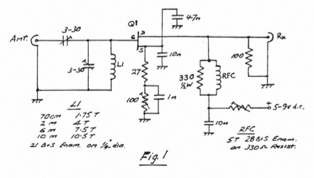
The design presented here (Fig.1) is quite straightforward, using a parallel reso- nant front end which also provides a DC path to ground, giving some protection for the FET. Signals in the passband of the tuned circuit are amplified by the device to the output. A ferrite bead on the Drain lead, in conjunction with a 100 ohm shunt restricts interference from the DC supply restricts interference from the DC supply and passifies the output impedance. DC is applied the Drain via rf choke to an consisting of 6 turns of 28g enamal wire wound around the body of a 330ohm 1/4 watt resistor.
The noise figure of this amplifier is well below 0.5dB (dependent on frequency) when used in conjunction with a well regulated and filtered 4 to 9 volt dc supply.
Variations:
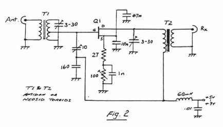
Small toroidal transformers can be used for input and output matching if desired (refer Fig.2). This method also provides degree of protection for the device and the secondary winding can be tapped at 1.5 turns from the ground end to present a low impedance source. They can also be an aid to stability. If you choose to use toroids however, be aware that they are frequency conscious and need to be chosen carefully.